|
|


P13. Electric circuits
13.1 Circuit Diagrams
13.2 Series and parallel circuits
|
|
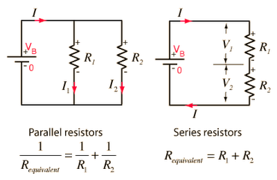
There are two different ways of circuits, of connecting resistors (e.g. lamps) to the same battery. These circuits are called series and parallel circuits.
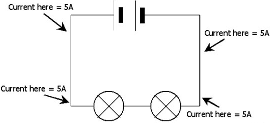
A series circuit is a circuit in which resistors are arranged in a chain, so the current has only one path to take.
A series circuit is a circuit in which resistors are arranged in a chain, so the current has only one path to take.
- The current is same through each resistor in series circuit.
- The total resistance of the circuit is found by simply adding up the resistance values of the individual resistors. Equivalent resistance (R) of resistors in series circuit can be expressed by:
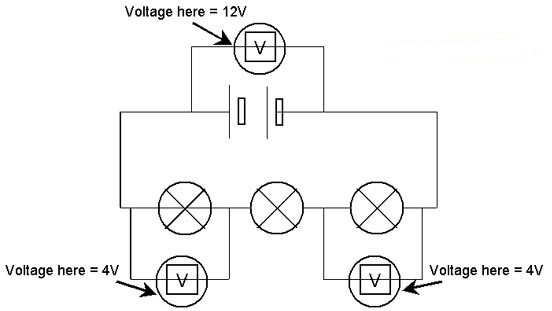
- In series circuit the total potential difference (V) of individual resistor is the sum of individual potential differences. That is
- The current (I) remains the same in each resistance therefore the ammeter is connected in series with the other resistances.
- A parallel circuit is a circuit in which the resistors are arranged with one end of each resistor connected together, and other end of each resistor connected together and then each end connected directly to the battery.
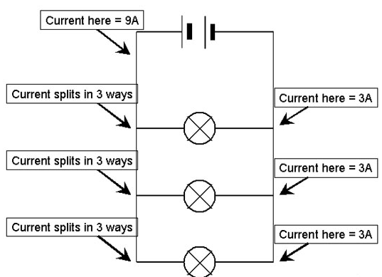
- The current in a parallel circuit breaks up and take the easiest path first, with some flowing along each parallel branch and re-combining when the branches meet again.
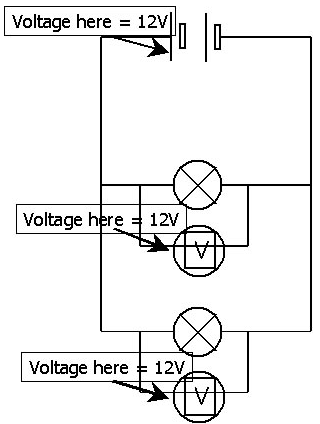
- The voltage across each resistor in parallel circuit is same. Equivalent resistance of resistors in parallel circuit can be expressed by:
- 1/R = 1/R1 + 1/R2 + ...
- In parallel circuit the total current is the sum of individual currents in each resistance. I=I1 +I2+...
- Voltage in each resistor remains the same across each resistor; therefore the voltmeter in parallel circuit is always connected in parallel with other resistances.
- The combine resistance of all the resistances is less than the individual resistance.

Click to explore a tutorial on Parallel Circuits
13.3 Action and use of circuit components
|
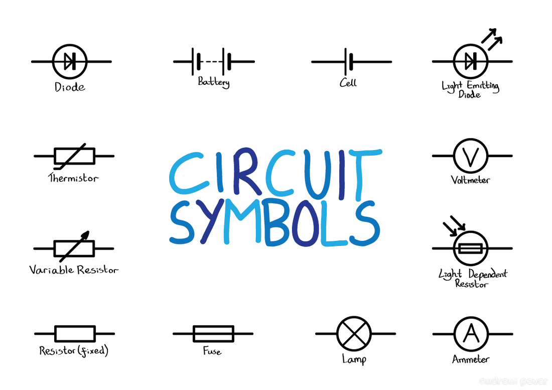
You should be able to recognise the circuit symbols for the thermistor and the LDR (light-dependent resistor), and know how the resistance of these components can be changed.
The thermistor
The LDR
Relays
|

Thermistor symbol

LDR symbol
Relay symbol
|
Revision
Electric Circuits revision site