|
|


P8. Light

| Chapter on light waves |
8.1 Reflection of light
|
In the diagram, the ray of light approaching the mirror is known as the incident ray and the ray of light that leaves the mirror is known as the reflected ray.
At the point of incidence where the ray strikes the mirror, a line can be drawn perpendicular to the surface of the mirror. This line is known as a normal line. The normal line divides the angle between the incident ray and the reflected ray into two equal angles. The angle between the incident ray and the normal is known as the angle of incidence. The angle between the reflected ray and the normal is known as the angle of reflection. (These two angles are labeled with the Greek letter "theta" accompanied by a subscript; read as "theta-i" for angle of incidence and "theta-r" for angle of reflection.) |
The law of reflection states that when a ray of light reflects off a surface, the angle of incidence is equal to the angle of reflection. |
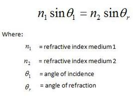
8.2 Refraction of light
| refraction_of_light_practical.pdf |
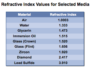
Refraction is the bending of the path of a light wave as it passes across the boundary separating two media. Refraction is caused by the change in speed experienced by a wave when it changes medium, e.g. from air to water.
Light can either refract towards the normal (when slowing down while crossing the boundary) or away from the normal (when speeding up while crossing the boundary).
Light can either refract towards the normal (when slowing down while crossing the boundary) or away from the normal (when speeding up while crossing the boundary).
|
|
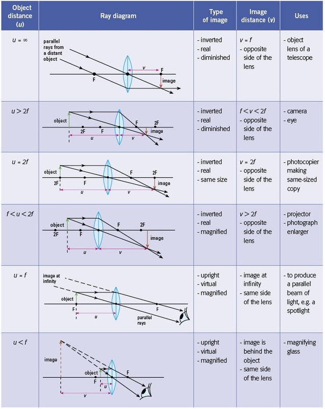
8.3 Thin converging lens
A lens is basically a transparent object that causes the light that passes through it to refract.
Converging lens that are curved on both sides will cause light that are travelling parallel to the Principle axis (a horizontal line passing through the middle of the lens) to refract and cross the Principle axis at a fixed point known as the Focal point.
Converging lens that are curved on both sides will cause light that are travelling parallel to the Principle axis (a horizontal line passing through the middle of the lens) to refract and cross the Principle axis at a fixed point known as the Focal point.
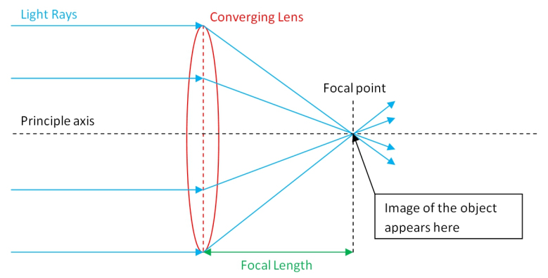
Principal focus (Focal Point) : is the point where rays of light travelling parallel to the principle axis intersect with the principle axis and converge (Fi on the diagrams below!)
Focal Length : is the distance between the centre of the lens and the focal point.
Focal Length : is the distance between the centre of the lens and the focal point.
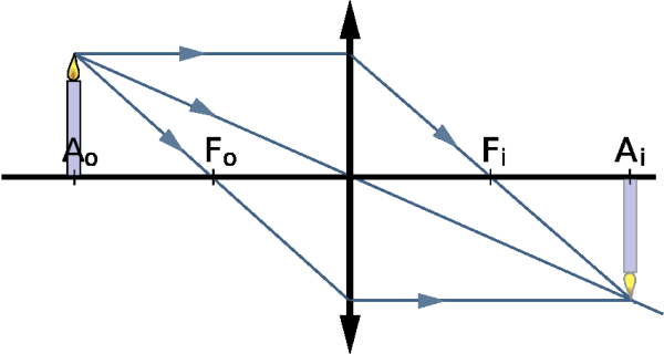
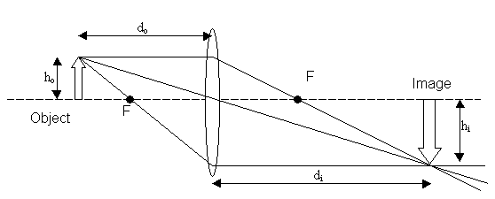
In the diagram above, the original image is at Ao, two focal lengths away from the lens. A real image of the same size is formed at Ai, two focal lengths away from the lens as well. However, the image is inverted.
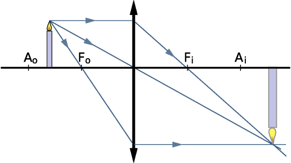
In the diagram above, the object is closer to the lens. The distance from the object to the lens is about 1 ½ focal lengths away. Since the object is closer to the lens, the real image of the object is produced further away, at 2½ focal lengths. This time, the image is bigger and inverted.
However, if the object is at one focal length (Fo) away, no image is produced.
However, if the object is at one focal length (Fo) away, no image is produced.
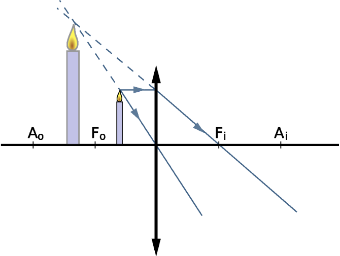
The diagram shows the formation of a virtual image. At distances less than one focal point, the refracted rays are diverging instead ofconverging. Hence, when we look at the object through the lens, it appears that the rays of light have come from a point behind the object (as shown by the dotted lines).
It is called a virtual image because it appears that the light comes a non-existent source further away than the real object. The virtual image produced is not inverted but upright and bigger than the original object and it appears on the same side as well.
Look at the first two diagrams above, you should notice these common things:
- Middle line passes through the origin (centre of the lens) in a straight line from the object to the image.
- Top line is parallel to the principle axis until it passes through the lens. The line then bends, passing through the focal point (Fi).
- Bottom line first passes through (Fo), one focal length away from the lens. When the line passes through the lens, it then travels parallel to the principle axis.
- Where the 3 lines converge is where the inverted image is formed.
|
|
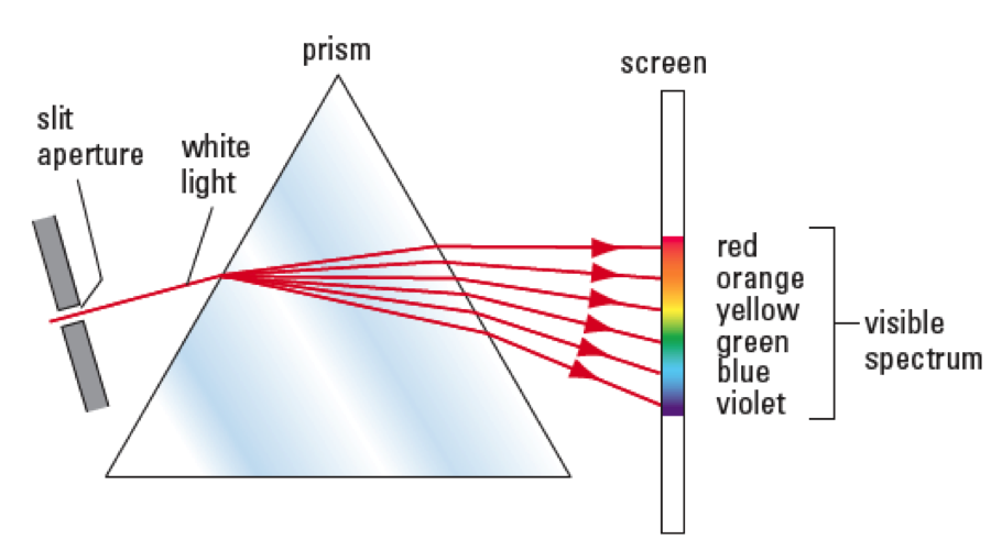
8.4 Dispersion of light
|
R- Red O- Orange Y- Yellow G- Green B- Blue I- Indigo V- Violet |

|
Revision